During operation, no cables can be connected or disconnected, and no buttons can be pushed.
Components under Consideration
| Component | Picture | Description |
|---|---|---|
| Choe Solar Panel |  |
CHOE 19W Portable Solar Charger http://www.amazon.com/gp/product/B00TEQJEC6 |
| Lithium Polymer Battery |  |
Polymer Lithium Ion Battery - 2000mAh https://www.sparkfun.com/products/8483 |
| Kmashi |  |
KMASHI 10000mAh USB power bank http://www.amazon.com/KMASHI-Thunderbolt-Incredible-Blackberry-Smartphones/dp/B00JM59JPG |
| Vogue |  |
Vogue 4500mAh USB power bank https://www.discountelectronics.com/product?product_id=20283 |
| Lipo Rider Pro |  |
Lipo Rider Pro http://www.seeedstudio.com/depot/LiPo-Rider-Pro-p-992.html |
| Adafruit Solar Lipo Charger |  |
USB / DC / Solar Lithium Ion/Polymer charger - v2 http://www.adafruit.com/products/390 |
| Sparkfun Sunny Buddy |  |
SparkFun Sunny Buddy - MPPT Solar Charger https://www.sparkfun.com/products/12885 |
| DROK 3V to 5V 1A USB Battery Converter |  |
DROK® Ultra Small Mini DC Power Module DC 3V to 5V 1A USB Battery Converter Step Up Module
|
| SSR Relay Board 2.5A |  |
|
| SainSmart step-up converter |  |
Observations
Banana Pro Power Consumption
The Banana Pro requires 5 Volts to operate. The voltage from a LiPo battery (up to 4.2 Volt) is not enough to power a BPro. The BPro draws about 300mA in normal operation. However, if the HDMI is enabled, the system will draw up to 1000mA during boot, specifically during the moment when the monitor switches from text mode to graphics mode.
Solar Panel and USB Power Bank
The easiest solution would be to use a solar panel with USB output and a USB power bank. The first requirement is that the load (microcontroller) can draw power the USB power bank while the panel charges the USB power bank.| Solution | Result |
|---|---|
| Choe + Kmashi |
FAIL
|
| Choe + Vogue |
PASS
|
The test shows that the Kmashi does not pass this test, leaving the Vogue. However, it cannot be used due to the reset issue (see below.)
Lipo Rider Pro
The LipoRider can charge the battery and run the BPro at the same time. However, it seems to do that very inefficiently. When the battery is so empty that the BPro stops running, it's voltage is at 3.30 Volt. When we connect the USB power, the ampmeter shows about 600mA. The BPro itself consumes about 300mA. So you should think that the other 300mA are used to charge the battery-wrong.

In the above test, we let the charging take place for eight hours while the BPro was running. After eight hours, the battery voltage had only increased to 3.34 Volts! If the LipoRider were to provide 250mA to the battery for eight hours, a 2000mA battery would be fully charged and at 4.20 volts. So in this scenario, the LipoRider wastes most of the energy internally.
Also, the Lipo Rider cannot power a device when only the USB power is plugged in.
When the BPro is on battery and the battery runs low, the BPro turns off. Now, if we connect power, the Bpro will not boot up. It will boot up when we turn the switch to OFF and ON.

With the DROK power module between the AF and the BPro, the BPro boots up and runs both
When the external power is connected, it starts out drawing about 980mA which is the set maximum charging power with a 2.2K resistor soldered over the built-in. Eventually, it will settle in a 410mA which means that the AF uses about 100mA just ti run, and about 300mA to power the BPro, Not too bad.
With the battery fully charged and the BPro not running, the AF should not draw any (or very low) current. Fortunately, this appears to be the case: the battery voltage is 4.19 Volts and the USB power meter shows 0 Amps.

How long does it take to charge a 2000mAh LiPo battery?
First, we are going to measure the voltage of the battery in this settled state, assuming that the battery is fully charged. The voltage is 4.19 volts. Next, we are going to remove external power and let the BPro run on battery until it dies and measure the battery voltage.
This voltage is 3.33 Volts.
In our circuitry, we will use a relay. One of the advantages is that the fail-safe more, namely no power to the relay, will result in the power to the BPro to be disconnected for sure. Here is a nice little mechanical relay that draws about 10mA:


http://www.frys.com/product/6401152
http://www.nteinc.com/relay_web/pdf/R40.pdf
Later, we may look into solid state relays (SSR) in order to reduce the current draw.
However, this method might lead to a behavior where the Bpro is constantly turned on and off without ever really running. Here is why: Suppose the battery voltage is just below VOFF and the relay is off. the sun goes up and charges the battery above VOFF and the Bpro boots up. During the boot, the BPro draws so much current that the battery voltage imediately goes below VOFF and the relay shuts the power to the Bpro off. This allows the battery voltage to go above VOFF again in a short period of time, and the process repeats.

In our case, we have two battery voltages:
For a Lithium-Polymer battery, we might choose
VOFF = 3.4 Volt
VON = 3.9 Volt
http://www.ti.com/product/lm3914
and here is a video that explains how the battery voltage level circuit works:
Designing a Li-Ion Battery Gauge with the LM3914 - EEVblog #204
Here is the circuit modification that works for voltages from 3.0V to 4.2V:
https://github.com/xioTechnologies/LiPo-Battery-Meter

http://www.allaboutcircuits.com/worksheets/latch-circuits/
TI makes the set-reset latch chip CD4044B:

Now we connect the 3.4V logic output to the Reset input of the latch and the 3.8V logic output to the Set input of the S/R Latch to achieve the hysteresis:

The last step is to use the S/R Latch output to control the relais. The power of the latch is too weak to driver the mechanical relay. Usually, people use a transistor to drive a relay from a CMOS chip. In the mean time, the solid state relay (SSR) board from Phidgets has arrived, and it does work directly with the latch. For a quick test, we will use the SSR to drive the mechanical relay, and then of course we get rid of the mechanical relay and replace it with the SSR.

in the next step, we have replaced the mechanical relay with the solid state relay (SSR) and moved the 4044 chip onto the field board:

well, the SSR board got hot and started smelling, and the BPro didn't power up, so let's give the mechanical relay another chance. It however needs a transistor to drive:

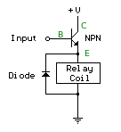
http://www.bowdenshobbycircuits.info/r_ctrl.htm

Here is the complete board:


In the above test, we let the charging take place for eight hours while the BPro was running. After eight hours, the battery voltage had only increased to 3.34 Volts! If the LipoRider were to provide 250mA to the battery for eight hours, a 2000mA battery would be fully charged and at 4.20 volts. So in this scenario, the LipoRider wastes most of the energy internally.
Also, the Lipo Rider cannot power a device when only the USB power is plugged in.
When the BPro is on battery and the battery runs low, the BPro turns off. Now, if we connect power, the Bpro will not boot up. It will boot up when we turn the switch to OFF and ON.
Adafruit Solar Lipo Charger
The AF puts out whatever the battery voltage is, so between 3.3 Volt and 4.2 Volt. This is too low for the BPro to run. We need an extra boost converter to power the BPro.

With the DROK power module between the AF and the BPro, the BPro boots up and runs both
- when the battery is connected and no power to the AF is connected
- when the battery is connected and the USB power is connected.
When the external power is connected, it starts out drawing about 980mA which is the set maximum charging power with a 2.2K resistor soldered over the built-in. Eventually, it will settle in a 410mA which means that the AF uses about 100mA just ti run, and about 300mA to power the BPro, Not too bad.
With the battery fully charged and the BPro not running, the AF should not draw any (or very low) current. Fortunately, this appears to be the case: the battery voltage is 4.19 Volts and the USB power meter shows 0 Amps.

How long does it take to charge a 2000mAh LiPo battery?
First, we are going to measure the voltage of the battery in this settled state, assuming that the battery is fully charged. The voltage is 4.19 volts. Next, we are going to remove external power and let the BPro run on battery until it dies and measure the battery voltage.
This voltage is 3.33 Volts.
The Reset Issue
When the BPro runs on battery and drains the battery down to 3.3 Volts, the BPro will shut down. Now if we apply power (through the solar panel, USB, power supply) and the battery voltage goes up again, the BPro will not boot. This is the case for all charge controllers tested. Therefore, we need extra circuitry to make the BPro boot when external power becomes available and the battery charges up again.Relay Control
The test with the LiPo Rider has already demonstrated that if we switch the power to the BPro off and on, that then the BPro will reboot.In our circuitry, we will use a relay. One of the advantages is that the fail-safe more, namely no power to the relay, will result in the power to the BPro to be disconnected for sure. Here is a nice little mechanical relay that draws about 10mA:


http://www.frys.com/product/6401152
http://www.nteinc.com/relay_web/pdf/R40.pdf
Later, we may look into solid state relays (SSR) in order to reduce the current draw.
Simple Solution Idea that does not work
The first impulse would be to add a comparator that disconnects the BPro power via a relay when the battery voltage goes below a certain value, for example VOFF=3.6 Volts and connects the power when the battery goes above that value.However, this method might lead to a behavior where the Bpro is constantly turned on and off without ever really running. Here is why: Suppose the battery voltage is just below VOFF and the relay is off. the sun goes up and charges the battery above VOFF and the Bpro boots up. During the boot, the BPro draws so much current that the battery voltage imediately goes below VOFF and the relay shuts the power to the Bpro off. This allows the battery voltage to go above VOFF again in a short period of time, and the process repeats.
How the Load affects the Battery Voltage
We apply a load of 620mA (4.7Ohm 10 Watt resistor) we discharge the battery until it shows 3.33Volts. When we remove the load, the voltage show 3.46Volts. Now if we connect the USB charger and a charging current of 970mA flows, the measured voltage is 3.6Volts.Reset Issue Solution: Hysteresis with Voltage Window
Obviously, we need a modification that will delay the turning off and on of the BPro, and we choose the battery voltage as the variable that determines the on-off condition. This modification is known as "hysteresis", for example with thermostats. When you set the thermostat to 70° the system will let the temperature drop to 69° before it turns the heater back on.
In our case, we have two battery voltages:
- VOFF where the relay turns the BPRo off
- VON where the relay turns the BPRo on
For a Lithium-Polymer battery, we might choose
VOFF = 3.4 Volt
VON = 3.9 Volt
Battery Voltage Measurement
First, we need to find a way to to generate logic signals depending on the battery voltage. Fortunately, a very nice chip already exists that can be used for our purposes: the LM3914http://www.ti.com/product/lm3914
and here is a video that explains how the battery voltage level circuit works:
Designing a Li-Ion Battery Gauge with the LM3914 - EEVblog #204
Here is the circuit modification that works for voltages from 3.0V to 4.2V:
https://github.com/xioTechnologies/LiPo-Battery-Meter

Hysteresis
We will need some kind of memory in order for the circuit to remember whether the most recent voltage threshold pass was at VON or VOFF. The simplest 1-bit memory is a set-reset latch,http://www.allaboutcircuits.com/worksheets/latch-circuits/
TI makes the set-reset latch chip CD4044B:

Now we connect the 3.4V logic output to the Reset input of the latch and the 3.8V logic output to the Set input of the S/R Latch to achieve the hysteresis:

The last step is to use the S/R Latch output to control the relais. The power of the latch is too weak to driver the mechanical relay. Usually, people use a transistor to drive a relay from a CMOS chip. In the mean time, the solid state relay (SSR) board from Phidgets has arrived, and it does work directly with the latch. For a quick test, we will use the SSR to drive the mechanical relay, and then of course we get rid of the mechanical relay and replace it with the SSR.

in the next step, we have replaced the mechanical relay with the solid state relay (SSR) and moved the 4044 chip onto the field board:

well, the SSR board got hot and started smelling, and the BPro didn't power up, so let's give the mechanical relay another chance. It however needs a transistor to drive:


http://www.bowdenshobbycircuits.info/r_ctrl.htm
 |
 |
 |

Here is the complete board:

ReplyDeleteLooking at the entire business world, only the foremost reliable products have decent warranties that cover damages and wear and tear. Warranties are often very useful if you've got a decent budget or are on a road trip and end up in need. By having the simplest automobile battery , available you recognize that you simply are going to be ready to get a replacement for much but you paid initially, if not free, within the event that you simply are light on funds and are in desperate need of a replacement battery.
professional battery manufacturer